Substation configuration and build types
Substation configuration and build types
Each substation, whether existing or new, can have different configurations or equipment construction depending on what is needed, and to comply with regulations. Here we look at the different types of substations customers can connect into.
Useful key terms and equipment definitions:
- Security and Quality of Supply Standard (SQSS): the minimum design standard used to plan transmission assets. It ensures safe and reliable operation across the transmission network.
- Substation bay: connects circuits to substations, linking generation sources or high-demand consumers, with switchgear and transformers included.
- Switchgear: comprises disconnectors, earth switches, and lightning arrestors in substations, ensuring safe circuit disconnection during faults or maintenance.
- Circuit breaker: A piece of switchgear that opens to break the circuit should a fault be detected, preventing the flow of electricity. A circuit breaker must be closed to resume normal operation of a circuit.
- Busbar: a conductive bar that allows multiple circuits to be connected, distributing electricity between the circuits.
- Earthing: equipment critical to electrical safety, allowing electricity to be directed to ground during a fault, as well as allowing for equipment to be safely maintained when switched out and other adjacent assets are still live.
- Transformers: steps up voltages to allow for efficient transmission of electricity over long distances, and steps down voltages for local distribution.
Depending on several factors, substations are often built to different equipment specifications. For example, the layout may be determined by the size or shape of the specific site, or by the type of connection that has driven the need for the site.
Single busbar
In this configuration, equipment connects directly to a single busbar, allowing for efficient use of space and economical operation. While it is simple to maintain, a fault or maintenance can disconnect all connected bays. Each bay has individual circuit breakers, so if one customer’s equipment trips, the rest remain unaffected.
Users can choose to connect into single busbar substations, however given the limitations of this kind of connection arrangement, it would be subject to the User agreeing to a variation to connection design in accordance with the SQSS.
Double busbar
A double busbar configuration connects equipment in bays to two busbars, allowing flexibility in maintenance and fault management by transferring loads to a reserve busbar.
Each customer has individual breakers for safety. While it requires more space and capital, it typically complies with SQSS due to reserve power availability.
Mesh corner substations / compact mesh design substations
Mesh corner substations have a single busbar, which is arranged in a ‘square’ with four circuit breakers located to create isolatable corners. One corner can be taken out of service for maintenance, with the other corners remaining live. Owing to issues with the design behind a mesh corner arrangement, any fault generated on a feeder circuit into the substation, or on the generation connection itself, would have the potential to trip all the equipment connected. This means they fall below the new minimum design standards for planning the transmission system, and customers connecting at these sites must have a non-firm or design variation as they are not compliant with SQSS.
Mesh corner substations are typically found at 275kV on the Electricity Transmission System and were constructed under previous network design methodology, which differs from today. New mesh corner substations are not constructed due to these limitations.
Equally, most of these existing sites are in space constrained locations making extensions or modifications for connections extremely difficult.
Air insulated substations (AIS)
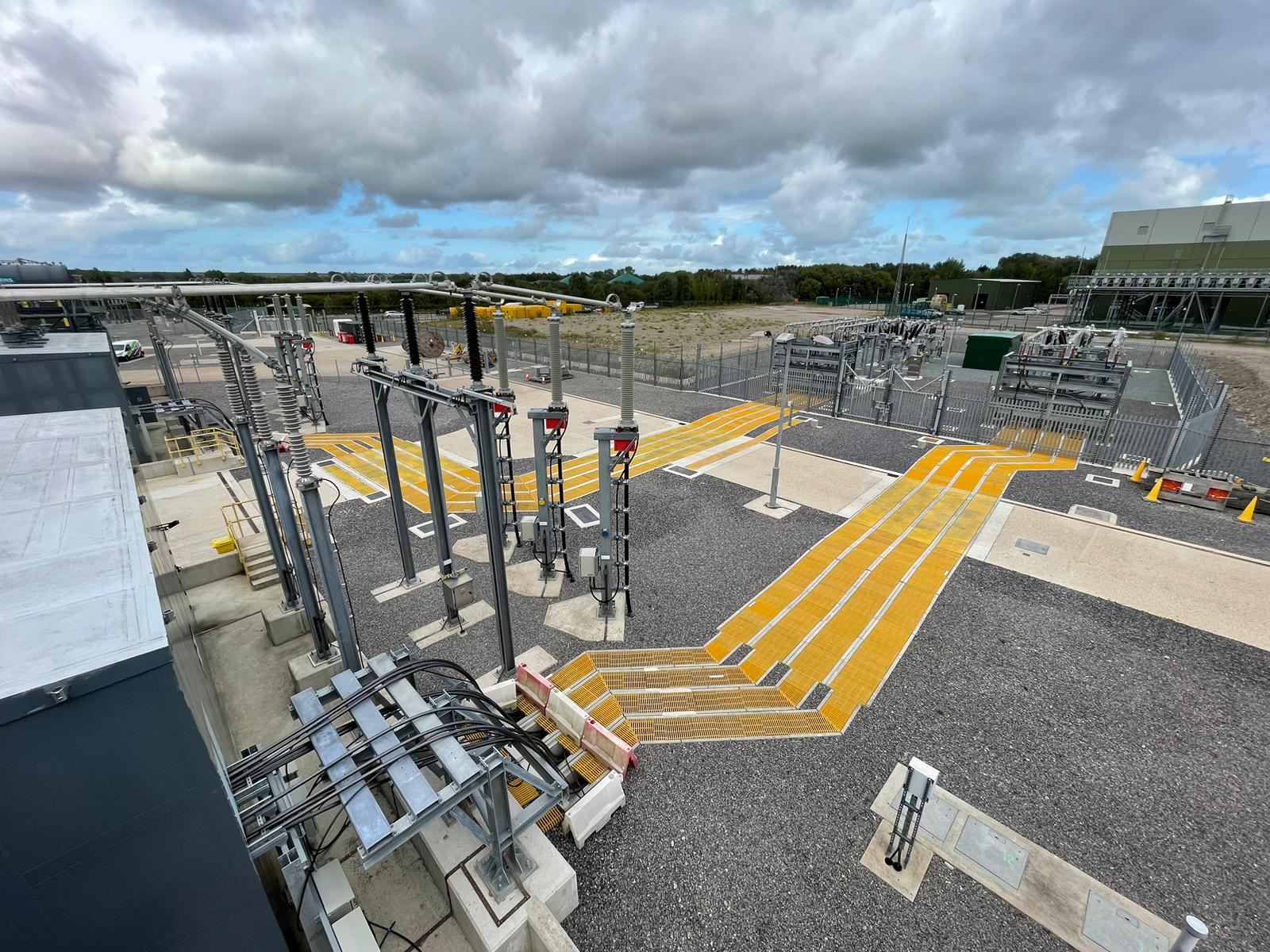
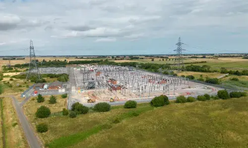
AIS sites use the physical air gap between equipment as insulation, typically built in large, open spaces. They are economical to construct, as they don’t require insulating gases and have minimal buildings.
AIS allows for individual electrical isolation of primary plant components for troubleshooting. However, they occupy a larger footprint than gas insulated substations (GIS). Maintenance is resource-intensive due to the need for visual inspections, but faults are easier to identify and resolve compared to GIS.
Gas insulated substations (GIS)
GIS traditionally use Sulphur Hexafluoride (SF6) gas for insulation, but efforts are underway to phase it out for alternative gases. GIS occupy a smaller footprint than AIS, allowing construction in space-constrained areas. They can be monitored remotely, reducing the need for visual inspections; however, expert maintenance is necessary to isolate and de-pressurise systems for fault identification.
GIS are more expensive to build due to gas costs and containment buildings, and sealed breakers require complete replacement if they fail. New GIS assets often feature double busbar configurations for increased efficiency and customer accommodation.
For more information on our new substation triggering and expansion processes, read our article on how we locate new substations.


